Operating Principles and Structure

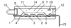
Fig.1 Cut Model
The VFD is a kind of triode vacuum tube with three electrodes which are:
- Cathode Filament(s)
- Control Grids
- Illumination Anodes
The electrons emitted from the cathode filaments are controlled by the grids. When the grid is supplied with a positive voltage, it attracts the negative electrons, diffuses them and, due to their acceleration, many flow through the grid mesh towards the anode (opposite charges attract). However, when the grid is supplied with a negative voltage, it repels the negative electrons and prevents them from reaching the anode (similar charges repel).
The illuminating anodes are coated with phosphor which emits light when hit by the electrons. Each anode forms a segment or dot, which collectively form individual characters. When an anode is supplied with a positive voltage, it will attract the electrons which have been accelerated through the grid. The segment emits light when these electrons impact on the phosphor coating. Alternatively when anodes are supplied with a negative voltage, they will repel electrons from their phosphor coating and therefore remain un-illuminated.
By selecting combinations of illuminated segments, the desired digit or character can be formed.

Fig.2 Frame and Hybrid Type
| 1. | Glass Substrate (Anode Plate) | 10. | Getter |
|---|---|---|---|
| 2. | Conductive Layer | 11. | Face Glass (Cover Glass) |
| 3. | Anode (Base) | 12. | Spacer Glass |
| 4. | Insulation Layer | 13. | Evacuation Tube |
| 5. | Phosphor (Display Pattern) | 14. | NESA (or ITO) coating |
| 6. | Conductive Paste | 15. | Lead Pin |
| 7. | Grid Mesh | 16. | Mold Resin |
| 8. | Conductive Frit Glass | 17. | Solder |
| 9. | Filament (cathode) | 18. | Frit Glass |
Guide to VFD Operation


