Filament Power Supply
Filament Voltage
Luminance varies with the filament voltage (Ef) as shown in Fig.10. Since the lifetime of a VFD is dictated by the extent of evaporation of oxide materials coated onto the tungsten filament wires, it is critical that the filament voltage is supplied within the specified ratings.
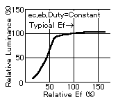
Fig.10 Luminance and Filament Voltage
Current drain from the anodes and grids to the filaments can cause ghost illumination so a bias voltage is applied to the filaments to raise them above ground. This is described later.
AC Filament Drive (50 or 60Hz)
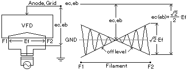
Fig.11 Transformer with Center-Tap
Generally, the transformer is the most popular device utilized to supply the filament voltage (Ef) with a 60(or 50)Hz sine wave which also has a center-tap for cathode bias as shown in Fig.11. The center - tap technique is used to prevent luminance slant i.e. difference in brightness from one side of the display to the other.
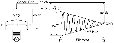
Fig.12 Transformer without Center-Tap
Using a transformer without this center-tap can not only cause luminance slant but also ghost illumination due to exceeding the amplitude of the filament voltage in excess of the specified cut-off bias voltage rating.
Pulse Filament Drive (High Frequency RMS)
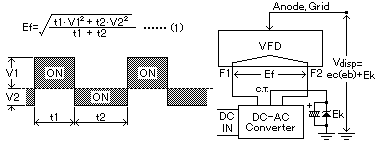
Fig.13 DC to AC Converter
In the case of a DC or battery power supply, a pulse wave form for the filaments can be generated from a DC to AC converter. The concept of pulse voltage supply to the filament is the same as AC filament drive. In either case Noritake still recommends the DC to AC converter with a center-tap as shown in Fig.13. Please note that the pulse voltage should be calculated as an RMS (root mean square) value from the wave form as shown in formula (1).
However, a 1/2 duty factor should be set, and the peak to peak pulse wave form should be 1.5 times or less than the RMS value. A frequency range of 10kHz to 200kHz is recommended.
DC Filament Drive
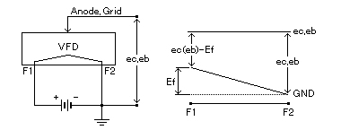
Fig.14 DC Filament Drive
If a DC filament drive is adopted, a potential difference between the anode and grid voltage will be apparent as a luminance slant across the display as shown in Fig.14. This shows brighter luminance at one side of the display due to the DC voltage drop. In order to avoid this problem, special measures are applied during display construction and the polarity (+,-) of the filament or grid terminal is specified. However, this is only possible for relatively short length VFD's.
Note : Please consult Noritake in advance before designing DC or DC pulse filament drive circuits.
Guide to VFD Operation


