Filament Bias Voltage (Cut-off Bias)
Cut-Off Characteristics (Grid/Anode Cut-off Voltages)

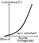
Fig.15 Anode Voltage and Luminance

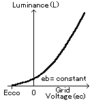
Fig.16 Grid Voltage and Luminance
Luminance (L) varies with the anode voltage (eb) as shown in Fig.15 when the grid voltage (ec) is a constant. Luminance also varies with the grid voltage as shown in Fig.16 when the anode voltage is a constant. To completely turn off the luminescence at the un-addressed display segments, a negative voltage shall be applied to the un-addressed anodes and grids with respect to the filament. These negative voltages are called anode cut-off voltage (Ebco) and grid cut-off voltage (Ecco) respectively. The cut-off voltage-varies depending on each type of display due to various differences in filament voltage and wave form. Please note that the cut-off voltage quoted in each particular specification is based upon the AC voltage being supplied via a transformer complete with center-tap.
Filament Bias Voltages (Ek)

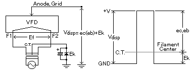
Fig.17 Cathode Bias
The filament bias voltage (Ek) is a voltage applied to the filament center-tap in order to cut off background illumination when the anodes and grids are not addressed. The 'off' anode and grid voltages remain negative with respect to the filament. The total supply voltage Vdisp is ec(eb) + Ek. ( In the case of CIG displays, the Ek is included in VDD2.)
In typical driving circuits, a zener diode supplies the Ek as shown in Fig.17. The cathode bias (Ek) for filament center-tap is higher than that specified for the grid cut-off voltage (Ecco). Usually, the Ek is set at the same value as MIN voltage of Ecco shown in the specification or a slightly large value when utilizing a filament center tap (F.C.T.). If a center-tap is not available, a virtual center-tap with resistors is one acceptable alternative.
Guide to VFD Operation


