VFD Driving Modes
Two drive modes are possible with VFD which are referred to as static and multiplexing. The mode is dependent upon the pin-out of the anode segments and grids of the specific VFD.
Static Drive
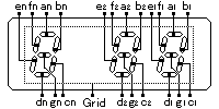
Fig.4 Static Drive VFD
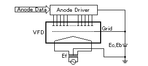
Fig.5 Driving Circuit of Static Drive VFD
In a static display, each anode segment is individually connected to a lead pin and a single grid covers all the display pattern in the VFD. This has the advantage in that it only requires 10 to 15 volts DC to illuminate the display and, in some cases, illumination is possible using standard 12 volts C-MOS logic. The major disadvantage with static mode is the need for more lead pins and IC drivers as the number of anode segments increases. Fig.4 and 5 show the basic construction and drive circuit.
Multiplex Drive (Dynamic Drive)
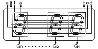
Fig.6 Multiplex Drive VFD
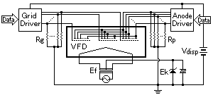
Fig.7 Driving Circuit of Multiplex Drive VFD
To minimize the number of pin connections and driver chips, the majority of VFD's use the multiplexing drive method. As shown in Fig.6, corresponding anode segments are connected in common under each separate grid, with each in turn being connected to a data line. Each character has its own separate grid which not only diffuses the electrons from the filaments, but also controls the selection of the character position in a "time share" multiplexing cycle. The duty cycle 'on time' of each character will determine the appropriate operating voltage required to provide sufficient luminance. Fig.7 shows the basic driving circuit.
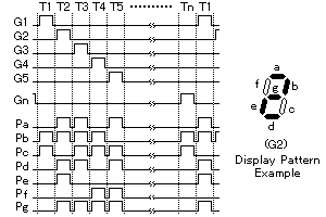
Fig.8 Example Timing Chart of Multiplex Drive VFD
The timing T1 in Fig.8 shows that when Grid 1 (G1) is ON and data lines Pb and Pc are ON under Grid 1, with all the other grids OFF, the numeric character '1' will be displayed. After the time period T1, Grid 1 is turned OFF and the voltages on the anode data lines are reconfigured to suit the requirements of Grid 2. Grid 2 is then turned ON. In the example, this will be the numeric character '2'. The scanning of Grid 1 to Grid n should be repeated at more than 100 times per second so that persistence of vision in the human eyes gives a stationary, solid display without any flicker. The number of grids and anodes is optimized to reduce the number of lead pins to a minimum. Other factors may be important so the multiplexing drive can be a duplex drive, where the display is separated under two grids, taking advantage of requiring fewer drive chips than static mode and a lower drive voltage than that required by an ordinary multiplexing mode.
Guide to VFD Operation