Power Supply
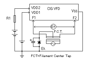
The power requirements of the CIG VFD are a filament supply (same as ordinary VFDs), logic supply voltage of "VDD1" and display voltage of "VDD2". The range of values typically required are shown in the following table. Please check the individual product specification for the specific values.

| Symbol | Terminal | Function | Notes |
|---|---|---|---|
| Ef | F1, F2 | Filament voltage according to specification. | 2Vac to 10Vac |
| VDD1 | VDD1 | For driver logic supply. 3.3V is available, please ask. |
5Vdc (3.3Vdc) |
| VDD2 | VDD2 | Grid / Anode Supply | 12Vdc to 72Vdc |
| EC | G | For static drive type only | 12Vdc to 72Vdc |
| EK | - | Filament bias voltage | 0V to 10V |
| GND | VSS | Ground of VDD1 and VDD2 | Ground 0V |
Filament Supply "Ef" and Bias Voltage "Ek"
Applying the correct filament voltage is the most important factor in extending the life of the VFD. Details on drive techniques and the filament bias voltage Ek required for the filament can be found in the application note on basic VFD operation.
Logic Supply Voltage "VDD1"

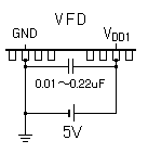
Fig. 7 Noise Filtering Capacitor for VDD1
The logic supply voltage is supplied to the logic circuit of the built-in drivers. Normally, +5V voltage is applied across terminals "VDD1" and "VSS". Always insert a noise filtering ceramic capacitor (0.01 to 0.22 uF) between VDD1 and VSS terminals in order to avoid false operations due to noise. Some types of VFD come with two pairs of "VDD1" and "VSS", as shown in Figure 7. In this case, apply the power to all the terminals of the two pairs and insert the filtering capacitor separately across each of the "VDD1" and "VSS" pairs.
Display Supply Voltage "VDD2" and R1
This power is supplied to the drivers for the display. Its voltage is applied to the internal grids and anodes through the driver outputs. For this type of VFD, +12V to +72V voltage is applied across the terminals "VDD2" and "VSS". The voltage defined in each individual specification should be applied. The rated value of this display supply voltage will have been calculated for optimized luminance and lifetime assuming the most standard service conditions . This voltage may be varied within the specified rated voltage range in order to adjust the basic brightness of the VFD (see note below). When low power consumption is required, the display supply voltage can be held low, with the resulting effect on brightness. Please contact our technical department to discuss this type of requirement as too low a voltage will result in uneven brightness. If you plan to control the brightness by software, it is suggested that you adjust it by varying the pulse width of the blanking input described later, and not by controlling the display supply voltage.
It should be noted that some multiplexed grid anode independent type CIG VFDs come equipped with two "VDD2" terminals, namely, "VDD2G" dedicated to grid drivers, and "VDD2A" for the anode drivers. Normally the same voltage is applied to "VDD2G" and "VDD2A", but some graphic type CIG VFDs may need to be supplied different voltages. Please check the individual specification for detail.
Many CIG VFDs require a current limiting resister in the VDD2 line in order to avoid false operation due to current surge. The resistance value of R is about 22 ohms. Please check the exact recommended value in each specification sheet. Do not connect a capacitor between VDD2 at the display and Ground (0V) as this will invalidate the resistor.
Grid Voltage "Ec" (for Static Drive Type only)

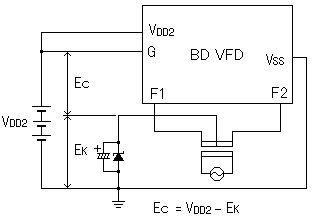
Fig.8 Grid Voltage
The grid voltage is applied to terminal "G" in a static drive type CIG VFD.(Figure 8) The rating of "Ec" on the specification represents the voltage between terminal "G" and the center-tap of the filament transformer (F.C.T.), and does not include the filament bias voltage "Ek". This means the base level of "Ec" and "VDD1 ","VDD2" are different on the specification. Normally, the same voltage "VDD2" can be applied to the terminal "G" directly. But in certain cases, the required voltage for "Ec" may be different from "VDD2". Please refer to the "Block Diagram" on the specification which shows how to connect the voltage for the "Ec" and the other supply voltages
Chip in Glass VFD (BD-VFD)
-
Operation and Structure
-
Power Supply
-
CIG VFD Interfacing
-
Control Procedure
-
Custom Design Guidance
-
Others


