Custom Design Guidance
Many aspects of custom design CIG VFD are identical to conventional VFD. This section aims to clarify the differences.
Lead Pins

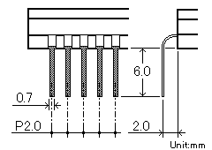
Fig 24. CIG VFD Lead Pins
The standard lead pin of the CIG VFDs is 6.0mm length and 2.0mm pitch. The dimensions of standard lead pin are shown in Fig. 24. Custom lead pin design is also available upon request.
Anode and Grid Size
The area of a segment must not exceed 300mm2 due to the limited current output capacity of the driver chip. When a large segment is required, it should be divided into two or three parts with each assigned to a different driver. A similar condition applies to grid size. Please consult our technical department for advice.
Driver Selection
The table shows the available CIG drivers and the maximum voltages (VDD2) including filament bias voltages. Optimize your design for the minimum number of devices to reduce the application cost.
| Driver | Number of Bit | Maximum Operating Voltage (VDD2 |
|---|---|---|
| Type 1 | 96 bit | 43V MAX, 58V MAX |
| Type 2 | 64+64 bit | 72V MAX |
| Type 3 | 4x32+16bit | 72V MAX with grey scale control |
Semi Custom Design
Saving in tooling cost and development time can be achieved by using pre-prepared metal parts and substrate. Please consult our design guidance on this subject.
Chip in Glass VFD (BD-VFD)
-
Operation and Structure
-
Power Supply
-
CIG VFD Interfacing
-
Control Procedure
-
Custom Design Guidance
-
Others


