Static Drive
Static Drive
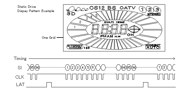
Figure 13 shows the data transfer protocol for a custom designed CIG VFD and is statically driven with one 96 bit driver. In a static driven CIG VFD, each input data bit of the shift register drivers is assigned to an anode segment in a one-on-one basis. The relevant assignment order is explained in the section called "Serial Data Format" or "Shift-Register Segment Assignment" in the individual specification.

Fig.13 Static Drive Data Transfer with a 96 bit driver
Each segment is controlled by sending data bits as "High" for ON or "Low" for OFF. The pattern data can be stored in output registers (latches) by applying the latch pulse so that the current pattern can be displayed while a new set of serial bits is clocked in for the next pattern. The data stream for a static drive display need only be active when the illuminated pattern has to change making it suitable for low RFI applications in radio and measuring instruments.
Chip in Glass VFD (BD-VFD)
-
Operation and Structure
-
Power Supply
-
CIG VFD Interfacing
-
Control Procedure
-
Custom Design Guidance
-
Others


